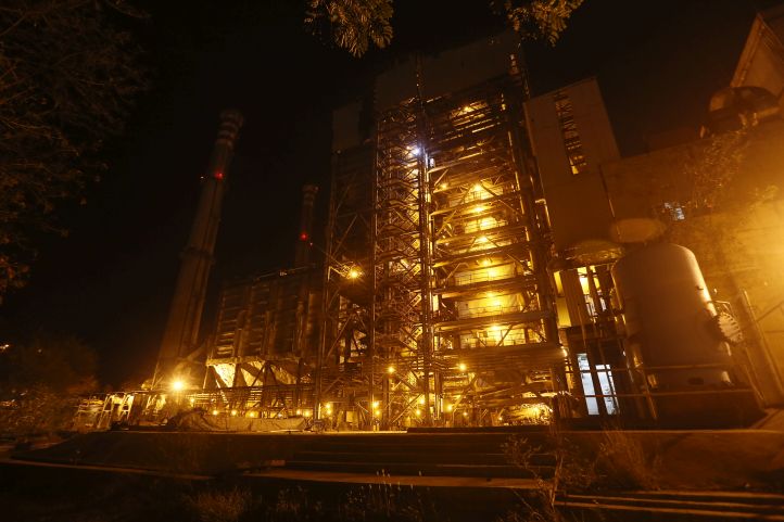
Tawa Hydro Electric Genration Power Plant

Net head of 21 meters (MWL) to 7.0 meters (at MDDL) is available at the foot of Tawa reservoir, when water is released either for irrigation or spilled to the river. This hydraulic potential is utilised for power generation at Tawa power house.
The reservoir water is passed through the approach channel to intake structure.
- Thrash rack prevents the entry of unwanted material into the water conductor system.
- Stop log gates maintain intake gates during high reservoir level.
- Automatic intake gates provide additional safety to the unit. They are designed to close in case of emergency.
- From intake structure the water directly enters the scroll case of the turbine units.
- Turbine speed is synchronised with the grid frequency through Hydro Electric governer, which operates the servomoter. Turbine acts as a prime mover to drive 11 KV, 28 pole synchronous generator . Power generated at the generator terminals varies from 1. 5 MV to 8.1 MV depending on the availability of net head and water discharge.
Power generated at the generator terminals is transmitted to the switch yard, where it is stepped to 33 KV by means of 9 MVA outdoor transformers. Excitation current is supplied to generators via resin cast Excitation transformers and static Excitation equipment. Two parallel transmission lines evacuate the power to the MPEB grid at Pathrota. Exhaustive protection system is provided on 110 V DC with battery backup. For any fault in the unit operations, alarm systems are automatically activated and the machines will trip depend on the severity of the fault. Both the units are fully automated and operations can be started / stopped from any stage through single button command either from MMI ( Man Machine Interface) or Auto Sequencer.
Instrumentation and Control Systems
Tawa unit is provided with centralised automatic instrumentation and control system.
The operations of the unit is performed from the Operator console of the Supervisory Control and Data Acquisition (SCADA) system provided in the control room.
The instrumentation and control system provides control over the entire power plan that includes starting, smooth running and stopping from the central control room.
Transducers / transmitters and other instruments are provided on various equipments of power house for generating analog and digital signals to meet the requirements of PLC system
Waste Heat Recovery System at Durg
Process
The waste gas when passed through a heat recovery steam generator made of radiant/conducive heat transfer surfaces, can generate steam qty. equivalent to about 11.8 TPH from each kiln depending on the kiln gas flow and temperature combinations.
In the FBC boiler air or gas is passed through an inert bed of solid particles with high velocity.The air bubles through the bed and particles attain state of high turbulence. The bed assumes the appearance of a fluid and is then heated to ignition temperature of fuel.
The fuel burns rapidly and the bed attains a uniform temperature due to effective mixing. The temperature of fuel should never be allowed to approach ash fusion temperature due to effective mixing. The temperature of fuel should never be allowed to approach ash fusion temperature to avoid melting of ash. This is achieved by conductive and convective heat transfer through tubes immersed in the bed. The Steam from WHRSG and FBC is brought to turbine through ESV.
Turbine Control & Protection (Automatic)
- Latest state of the art Microprocessor based fault tolerant systeminstalled for controlling the operation and safety of the turbine.
- Triple Modular Redundant (TMR) PLC system of Triconex Corporation USA helps in monitoring and controlling important process parameters.
- During critical process condition, turbine control is taken over by Automation till process is normalised
- Human machine interface and the data acquisition are through the SCADA system.
- System is having 100 milliseconds cycle time.
- Power is supplied to the automation system through a dual redundant UPS system
Generator Control & Protection
- Generator excitation is controlled by a micro processor based ultra fast IGBT powered AVR within cycle time of 400 milliseconds supplied by M/S CKD Czech Republic.
- Generator protection is achieved by multi functional microprocessor based programmable relays of Siemens, Germany.
Boiler Control & Protection
Controllers and the hot redundant PLC system of Simens are installed for automatic drum level control and combustion control of the FBC.